Turning Examples
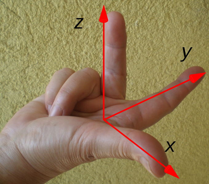
Programming for turning operations have always been graphically portrayed from the perspective of horizontal turning machines, i.e., +Z to the right, +X away. This perspective is 1) not in compliance with the coordinate system used by CAD, and 2) not in compliance with turning operations on vertical turning centers, and 3) not in compliance with machining operations in the G18 (X-Z) plane in milling operations.
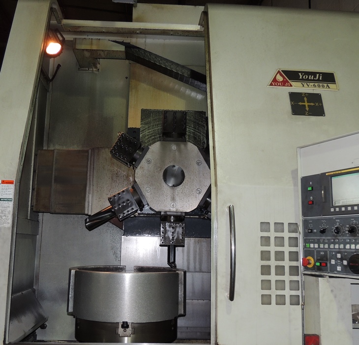
Programs written for vertical turning centers are identical to those written for horizontal turning. Because the vertical turning operation is viewed from the negative Y axis, there are two differences the programmer must be aware of: 1) what appears to be clockwise and counter-clockwise motion on a vertical turning center are actually G03 and G02 commands respectively in the CNC program and 2) cutter compensation that appears left and right on a vertical turning center are actually G42 and G41 commands respectively in the CNC program.
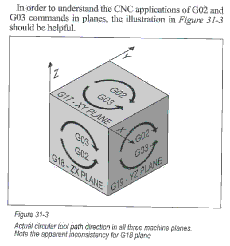
Peter Smid provides a comprehensive graphical depiction of arc motion and the associated G02/G03 commands for the G17/G18/G19 planes in his 2008 text book: "CNC Programming Handbook 3rd Edition.
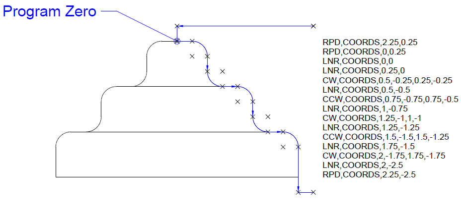
In the turning examples that follow, the front (X-Z) view in CAD will be used to develop CNC programs for turning operations.
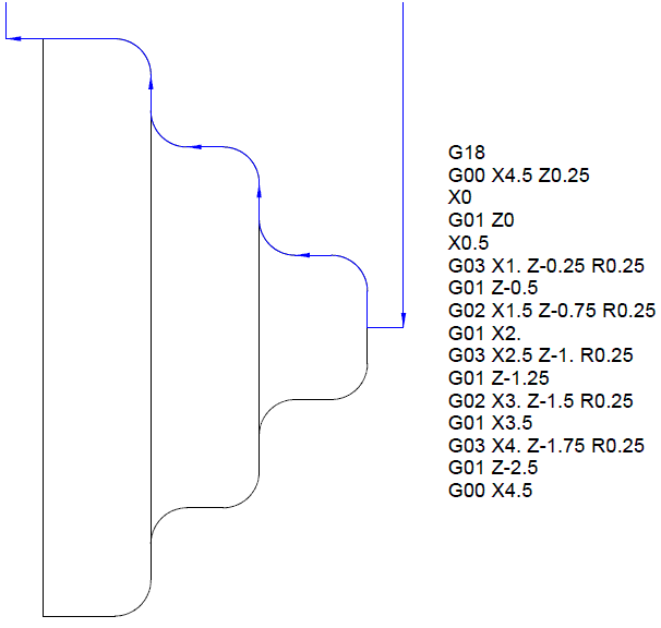
When converting CWS files to G-Code for turning operations and for milling operations in the X-Z plane, CNC Construct will automatically convert clockwise and counterclockwise motion in the CWS file to G03 and G02 commands, respectively.
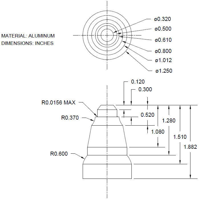
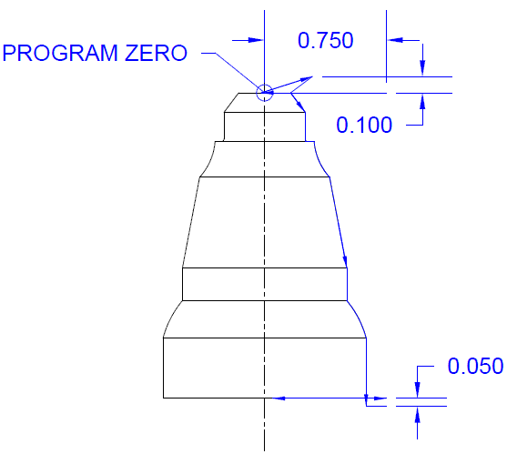
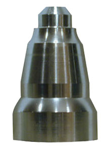
Programs written for vertical turning centers are identical to those written for horizontal turning. 1) The Part
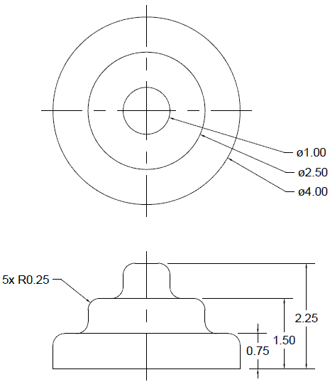
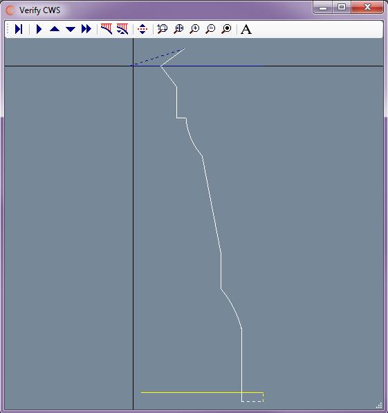
2) The Tool Path, points, and CWS information
3) The G-Code generated by CNC Construct
Assume this part is near net shape and all that must be done is to face the part, cut the finish pass on the profile using cutter compensation, and to part off to length.
- The part can be viewed by selecting the link below
- Program Zero will be top/center
- Assume cutter radius = 1/64" = 0.0156"
- The part off cutter will be set up to cut part length
- Use CAD to design the tool path for the face, tool path must go past X0 by at least the radius of the cutter (use -0.02")
- Use CAD to design the lead in and lead out to the profile, tool path must extend past the length of the part by the radius of the cutter or more
- Use CAD to design the lead for the part off tool, cut to X = 0.1" diameter and remove part manually
- On their own layers, use CAD to generate cutter coordinates for the face, the profile, and the part off
- Use CNC Construct to extract the coordinates from CAD and automatically create the CWS file
- Use CNC Construct to convert the CWS file to G-Code
- Use CNC Construct to paste the programming beginning, tool change, and program end commands from a template
- Use CNC Construct to edit the program as necessary
