CAD does Math
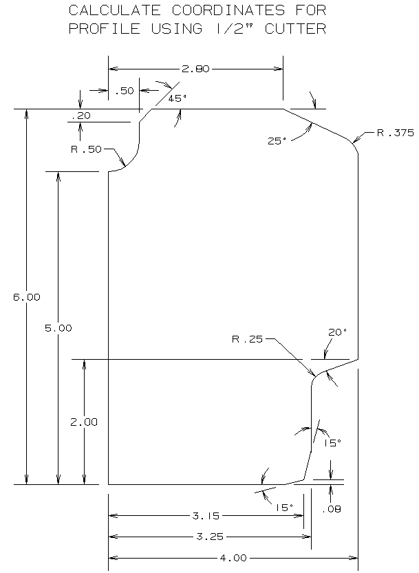
CAD is a powerful tool that gives the user the ablility to design parts, generate part drawings, and to design tool paths. By snapping points and lines on the parts and tool paths, then exporting to the IGES file type, CAD could have solved the math problem of manual CNC programming for planar, turning, and 2-1/2D milling operations.
Some believe that manual programming must be done without the aid of computers. This line of thinking is the equivalent to felling, limbing and bucking a tree with a hand saw, when an electric or gas powered chain saw could save so much time and labor.
Using power tools to perform manual operations is intelligent and accordingly, manual CNC programming should be done with whatever power tools can be incorporated to make the job easier, faster, and more accurate.
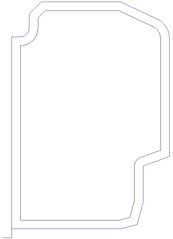
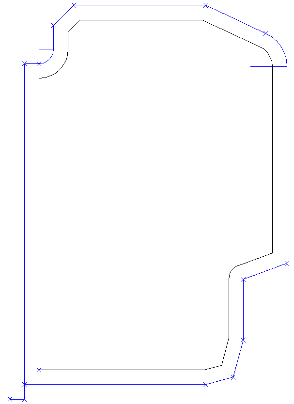
What follows is an example of how CAD can be used to design tool paths, and with the IGES file type, how CAD can generate a user friendly file that incorporates the coordinates of points and lines. Subsequently, these coordinates could be used for cutter coordinates and arc center coordinates for G-Code programs.
Three steps in sequence:
- Design finish tool path(s)
- Design last roughing path(s)
- Design all other roughing path(s)
Simple enough - and depending on the job, not all steps are required.
Eleven steps in sequence:
- Move entire part in CAD such that program zero for machining aligns with CAD zero
- If necessary, rotate part +/- 90 degrees around CAD zero such that part is oriented in CAD the same X-Y as on the machine
- Create a point at program zero
- In sequence of machining operation:
- Snap points at curve ends and intersections that correspond to rapid and linear motion
- Snap lines from intersections or curve ends to arc centers that correspond to clockwise and counterclockwise motion
- Save part
- Export drawing as IGES
- Open IGES file in Text Editor
- Scroll down or search for IGES point: 116,0.,0.,0.;
- Hope that the cutter coordinate point and line information was exported to the IGES file in the sequence they were created
- Copy and paste the point and line information of interest into new (blank) file in text editor
- Clean up file, edit coordinates as necessary, for example change absolute coordinates to incremental distances, and write the G-code program
View IGES File Type
View IGES Point and Line coordinates of interest
View the math that is required to get cutter coordinates
Using CAD to design tool paths, to generate points and lines, and to export the file to IGES is an obvious "mouse-click" technical advancement over doing the Math to get cutter coordinates.
IGES is the "missing link" that connects CAD to manual programming. And it has been a published standard since 1980.
But there is one major problem with IGES: Few CAD systems export this file type!
But if that were not the major problem, there are many other problems associated with using IGES:
- It is inconvenient to move the entire part in CAD such that program zero for machining aligns with CAD zero
- it is inconvenient to rotate a part +/- 90 degrees around CAD zero such that the part is oriented in CAD the same as on the machine.
- "Hope" should not be a step associated with G-code programming, but the IGES Standard does not require geometric objects be exported in the same sequence they were created
- No way to distinguish between linear and rapid motions
- No way to distinguish between clockwise and counter-clockwise motions
- No way to distinguish changes that might occur in the machining operation
- There is a considerable amount of extraneous data that is not necessary and requires considerable time to clean up
CNC Construct was developed to fix these and many other problems
CNC Construct does everything else
CNC Construct was developed to exploit both the inherent geometric power of CAD and the speed of computers to perform the most repetitive tasks and help programmers develop CNC programs as quickly, accurately, and easily as possible.


