Milling Examples
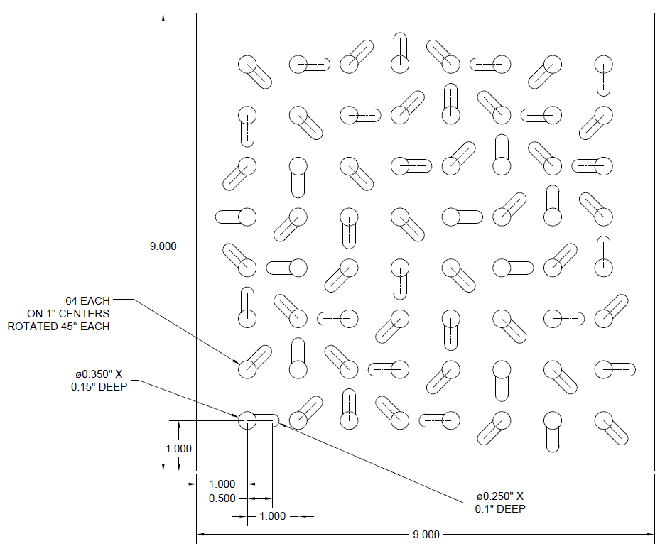
This programming demonstration is to show how G-Code cutter on commands can be used to enlarge a blind hole, aka - a counter-bore. As shown in the drawing, the feature that must be cut 64 times consists of a 0.35" hole at 0.15 depth followed by a 0.5" straight cut at 0.1" depth. Note that the 0.35" feature is repeated on 1" centers and the straight cut is rotated 45 degrees.
- The part can be viewed by selecting the link below
- Program Zero will be top surface/lower left corner
- A 1/4" diameter end mill will be used
- After the 0.25" diameter tool cuts to depth: Z-0.15, the hole must be enlarged 0.1" diametrically, or 0.05" radially for the 0.35" diameter requirement. The tool must then go back to center-line to cut the straight cut at depth: Z-0.1". The cutter on commands inserted 64 times will thus be:
- G01 Z-0.15
- G91 X0.05
- G03 I-0.05 J0
- G01 X-0.05
- G90 Z-0.1
- The cutter off commands will be G00 Z0.1
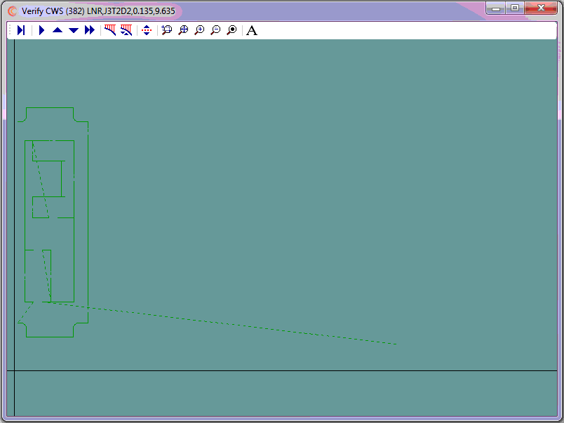
- On its own layer, use CAD to generate cutter coordinates for program zero and the 64 features
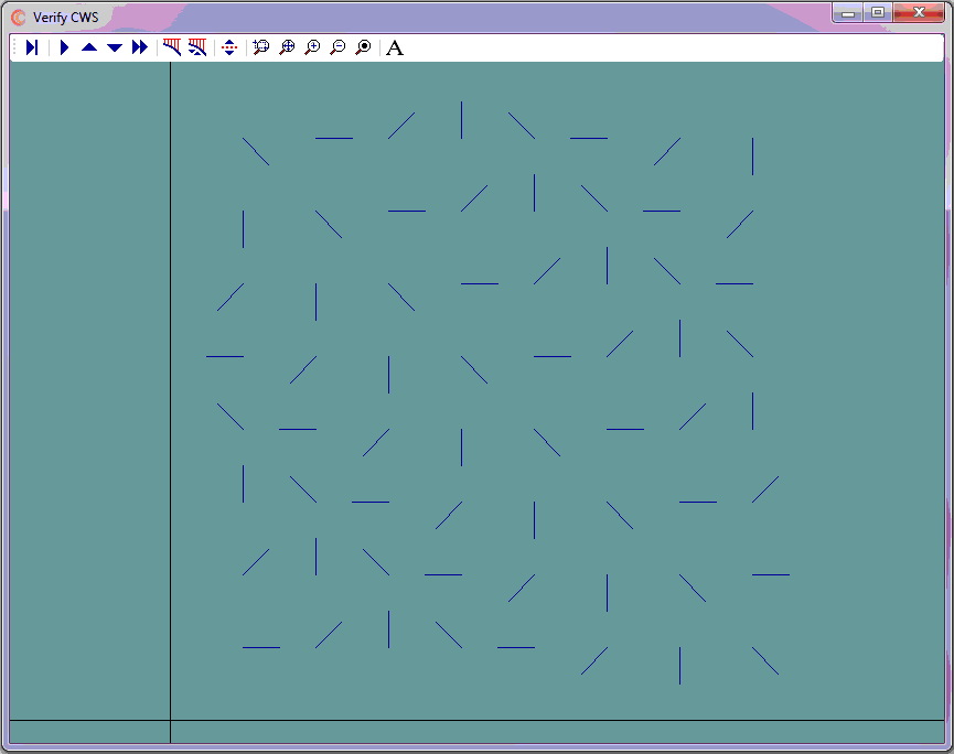
- Use CNC Construct to extract the coordinates from CAD and automatically create the CWS file
- Use CNC Construct to convert the CWS file to G-Code
- Use CNC Construct to insert cutter on/cutter off commands
- Use CNC Construct to paste the programming beginning and program end commands from a template
- Use CNC Construct to edit the program as necessary
Here is a note about programming time: Because no tool paths had to be designed, it took only 3 minutes to use CAD to snap all the necessary points on the center lines. It took less than one minute to use CNC Construct to complete steps 2 - 5.
View G-Code Program after program beginning and program end were inserted »
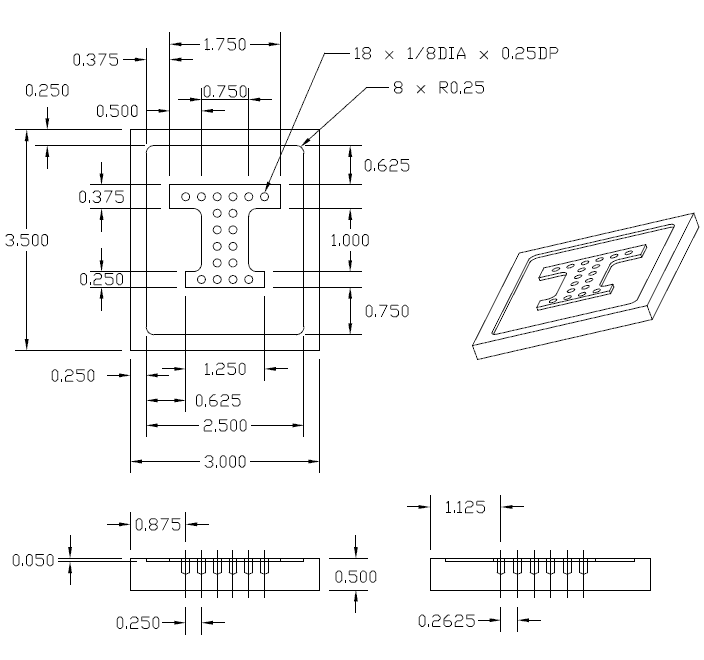
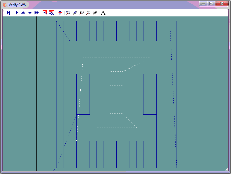
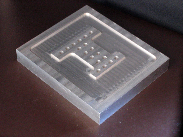
- The part can be viewed by selecting the link below
- Program Zero will be top/lower/left
- A 1/4" diameter end mill will be used for the pocket
- Cutter on/cutter off commands for the pocket will be G01 Z-0.05/G00 Z0.1
- A 1/8" diameter drill will be used for the holes
- Cutter on/cutter off commands for the holes are: G01 Z-0.25/G00 Z0.1
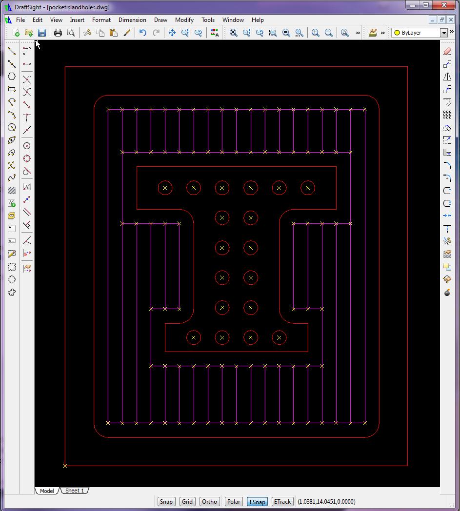
- Use CAD to design the tool path for the pocket
- On its own layer, use CAD to generate cutter coordinates for program zero and the pocket
- On its own layer, use CAD to generate cutter coordinates for the holes
- Use CNC Construct to extract the coordinates from CAD and automatically create the CWS file
- Use CNC Construct to convert the CWS file to G-Code
- Use CNC Construct to insert cutter on/cutter off commands
- Use CNC Construct to paste the programming beginning and program end commands from a template
- Use CNC Construct to edit the program as necessary
View G-Code Program Before Any Edits Made »
- The part can be viewed by selecting the link below
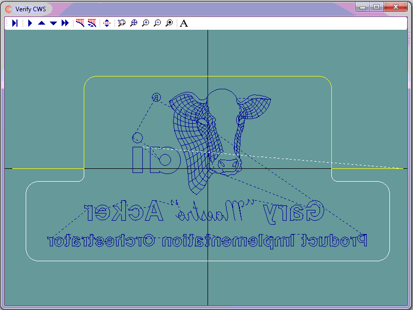
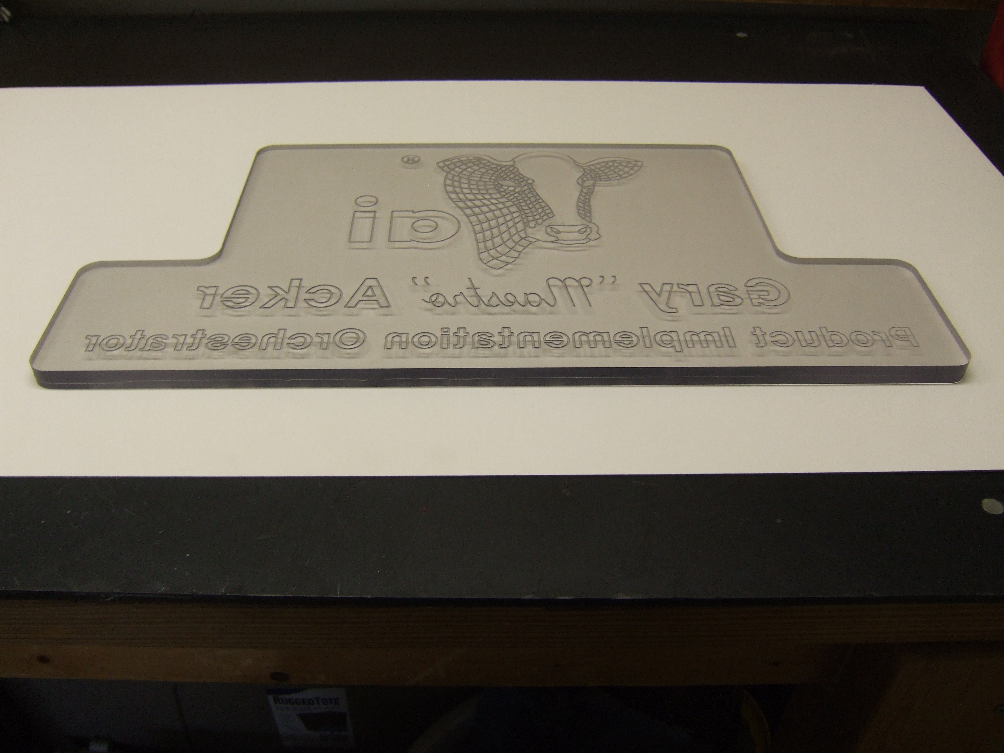
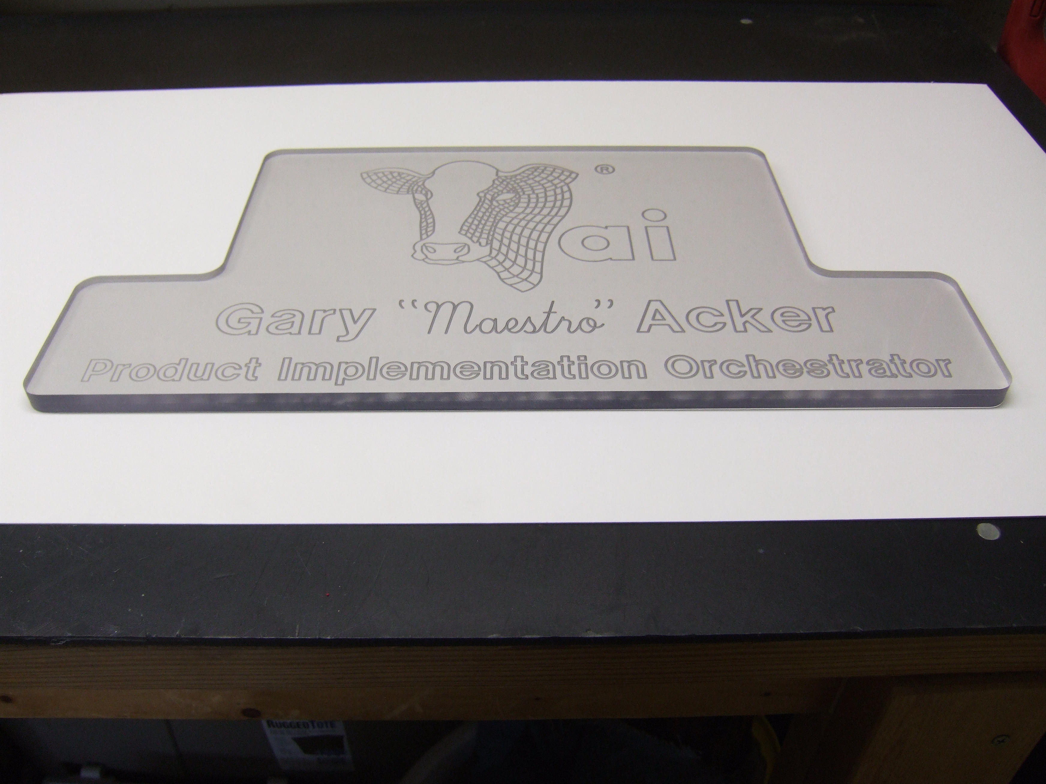
- The tool path is to be mirrored and cut on 1/2" thick acrylic
- Program Zero will be top/center
- A 1/16" diameter end mill will be used for the engraving
- A 1/2" diameter end mill will be used to cut the perimenter
- The part will be placed on 1/8" thick sacrificial material
- Cutter on/cutter off commands for engraving will be G01 Z-0.02/G00 Z0.1
- The perimeter will be cut in two passes, G01 Z-0.25, followed by G01 Z-0.505
- The lower perimenter will be cut first, clamps moved then upper perimeter will be cut
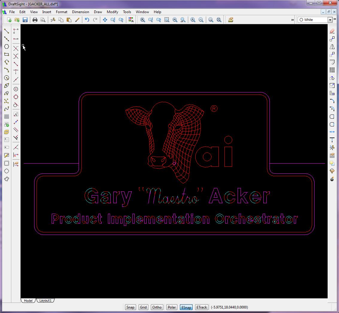
- Use CAD to copy, scale and move logo with cutter coordinates (generated in 5th planar example)
- Use CAD to generate the toolpaths and trace the text to arcs and lines
- Use CAD to generate the cutter coordinates as necessary
- Use CNC Construct to extract the coordinates from CAD and automatically create the CWS file
- Use CNC Construct to mirror the CWS file about the Y axis
- Use CNC Construct to convert the CWS file to G-Code
- Use CNC Construct to insert cutter on/cutter off commands
- Use CNC Construct to paste program beginning, tool change, and program end commands
- Use CNC Construct to edit the program as necessary
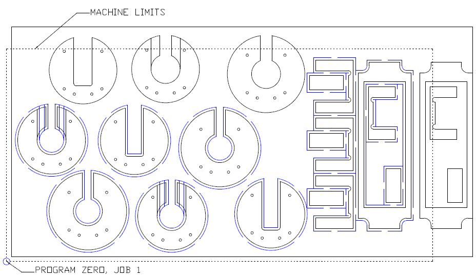
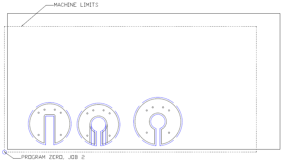
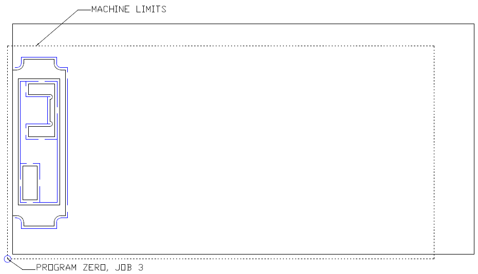
The sheet of material was approximately 24" x 12". The machine limits were 22" x 11". The part had to be machined, then flipped top to bottom, machined, then flipped left to right for the final operation. The toolpaths and the CNC program had to be developed accordingly
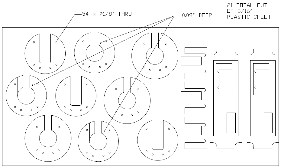
- The part can be viewed by selecting the link below
- This job has two cutters, a 1/8" dia drill and a 1/4" dia end mill
- The drill had one depth for 54 holes: -0.2"
- The end mill had two cutter depths, -0.09" for some part features and -0.2" for profiles
- To maintain structural intregrity of the sheet, each individual part had multiple tabs
The steps to complete this programming job were as follows:
- Use CAD to design tool paths
- On its own layer, use CAD to generate cutter coordinates for Job 1, program zero and the 54 holes
- On its own layer, use CAD to generate cutter coordinates for Job 1, tool 2, 0.09" depth
- On its own layer, use CAD to generate cutter coordinates for Job 1, tool 2, 0.02" depth around perimeter of parts
- On its own layer, use CAD to generate cutter coordinates for Job 2, program zero, tool 2, 0.09" depth
- On its own layer, use CAD to generate cutter coordinates for Job 2, tool 2, 0.02" depth around perimeter of parts
- On its own layer, use CAD to generate cutter coordinates for Job 3, program zero, tool 2, 0.02" depth around perimeter of the single part
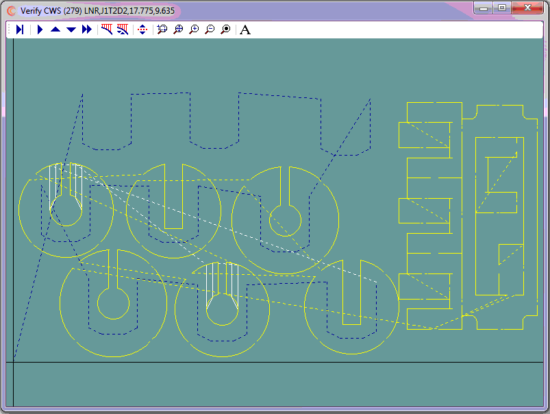
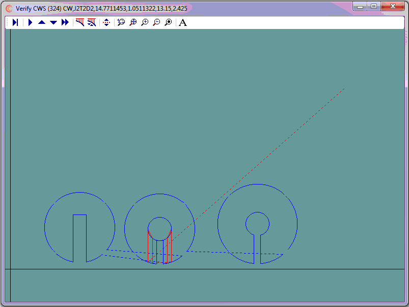
- Use CNC Construct to extract the coordinates from CAD and automatically create three CWS files
- Use CNC Construct to combine these three CWS files into one
- Use CNC Construct to convert the CWS file to G-Code
- Use CNC Construct to insert cutter on/cutter off commands
- Use CNC Construct to paste program beginning, tool change/program stop, and program end commands
- Use CNC Construct to edit the program as necessary
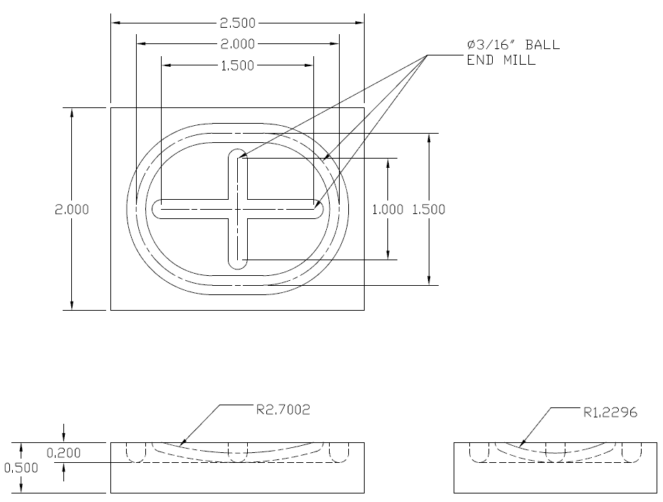
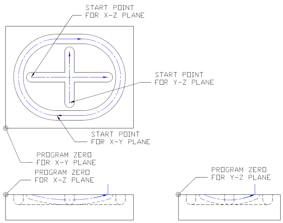
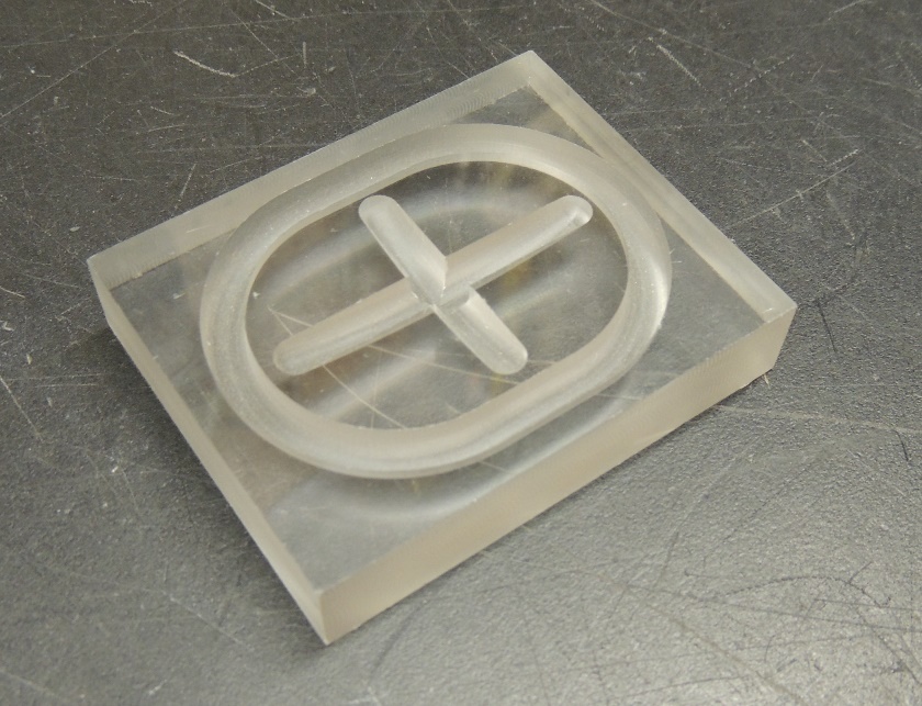
Milling operations are typically done in the G17 (X-Y) plane. But by using CAD and CNC Construct, it is possible to use the front view (X-Z) and the right side view (Y-Z) in 2-D CAD to generate CNC programs for planar operations in G18 (X-Z) and G19 (Y-Z) planes.
- The dimensioned part can be viewed by selecting the link below
- Center line programming of the 3/16" diameter cutter will be used meaning:
- The tooling will be set up such that a G01 Z0 command will cut into the part to the center line, i.e., -3/32" = -0.0938"
The steps to complete this programming job were as follows:
- Use CAD to design the tool paths
- On its own layer (XY), use CAD to generate cutter coordinates for Program Zero, and all necessary cutter coordinates in the X-Y plane
- On its own layer (XZ), use CAD to generate Program Zero and cutter coordinates for the arc in the X-Z plane
- On its own layer (YZ), use CAD to generate Program Zero and cutter coordinaes for the arc in the Y-Z plane
- Use CNC Construct to extract the coordinates from these three layers and automatically create three CWS files
- Use CNC Construct to convert each CWS file to G-Code
- Use CNC Construct to cut/paste and edit X-Z and Y-Z commands into the X-Y section of the program as necessary
- Use CNC Construct to paste program beginning and program end commands
- Use CNC Construct to edit the program as necessary
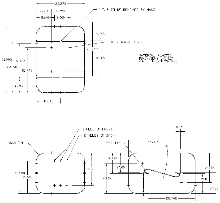
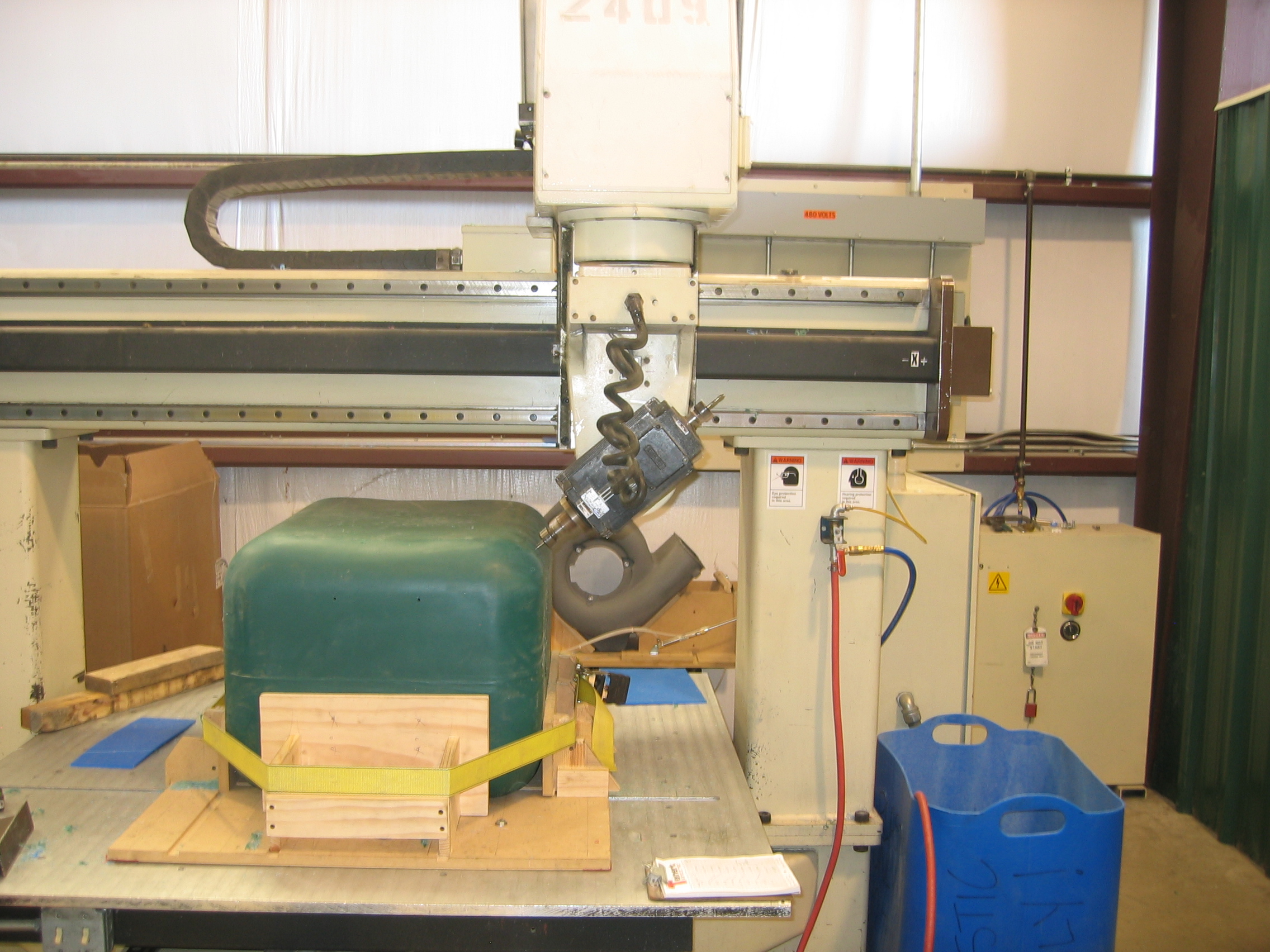
This is an an advanced programming example of how to use 2D CAD and CNC Construct to write a program to machine a prismatic part on a 5 axis Gantry Mill.
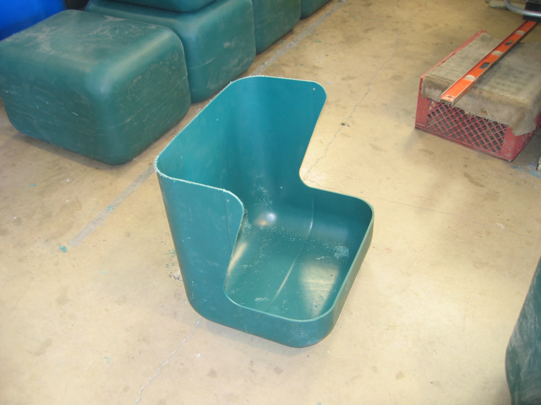
- The part can be viewed by selecting the link below
- The program is to be written to cut the top section of the part
- The part is to be rotated about the X axis and the program re-ran, i.e., the part is symmetrical
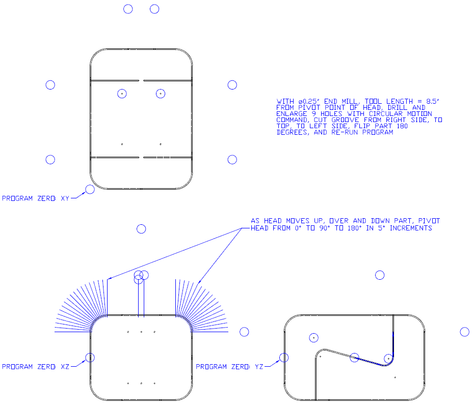
- A 0.25" diameter end mill will be used for both the holes and the groove
- The tip of the cutter will be set up at 8.5" away from the pivot point of the head
The steps to complete this programming job were as follows:
- Use CAD to generate the tool path
- Use circles to define the location of the holes in the top and right side views
- Use lines to define the distance from the tool tip to the cutter head pivot point in the front view
- On its own layer (XY), use CAD to generate the cutter coordinates for the X and Y axis for the 9 holes in the top view
- On its own layer (YZ-PTS) use CAD to generate program zero and the cutter coordinates for the Z axis for these 9 holes in the right side view
- On its own layer (YZ-GRV-FRT) use CAD to generate program zero and cutter coordinates for the counter clockwise groove on the right hand side
- On its own layer (XZ-GRV) use CAD to generate program zero and cutter coordinates for the groove going from the right side, over the top, down the left side using the the front view of the part
- On its own layer (YZ-GRV-BK) use CAD to generate program zero and cutter coordinates for the groove on the left hand side
- Use CNC Construct to extract these 5 layers to 5 CWS files
- Use CNC Construct to convert these 5 files to G-Code
- Use CNC Construct to cut, paste, and edit the G-code as necessary to do the drilling, enlarging, and groove cutting operation
- Use CNC Construct to insert the program beginning and program end commands
View CWS files as extracted by CNC Construct »
View Complete G-Code File »
