CNC Construct does everything else
CNC Construct was developed to exploit both the inherent geometric power of CAD and the speed of computers to perform the most repetitive tasks of G-code programming to develop CNC programs as quickly, accurately, and easily as possible.
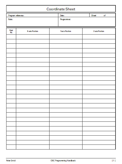
The problems with the unchanged 60+ year old coordinate sheets format are as follows:
- There are no columns that allow for the center coordinates of arc motions.
- There is no column for motion type.
- There is no column to prompt the programmer for changes in the program.
- The coordinate worksheet is a printed sheet of paper that must be completed by hand.
- Completing the coordinate sheet takes time that could be spent writing G-code.
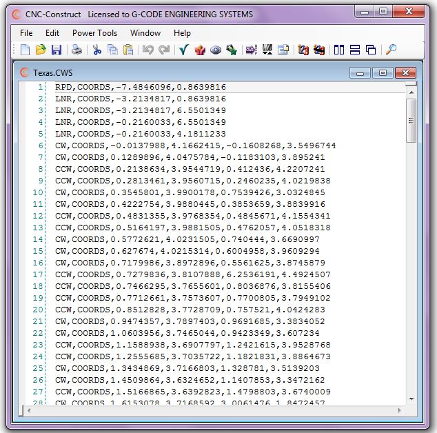
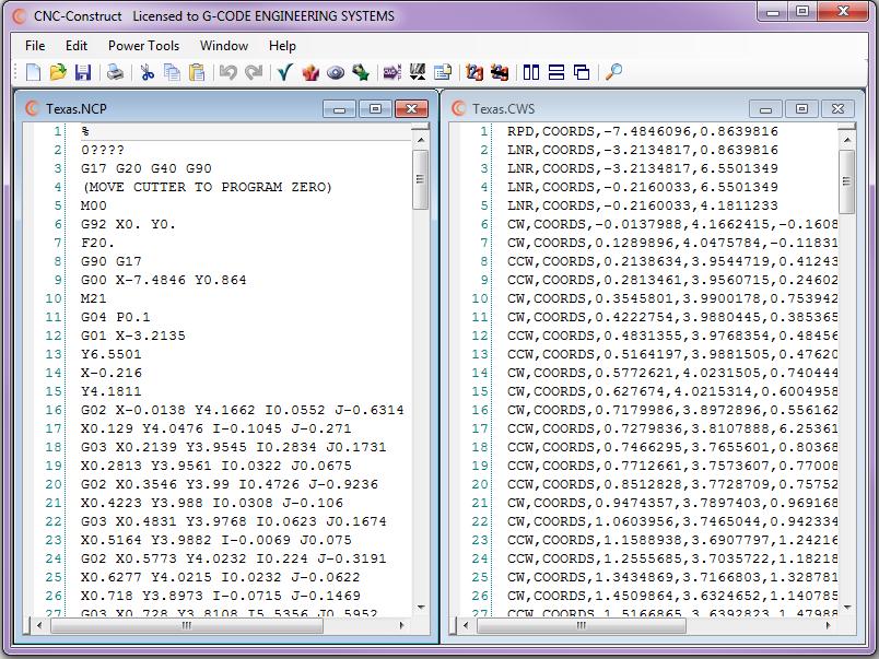
The solution to these problems is a comma delimited, ASCII based coordinate work sheet file type (*.cws) with the following format requirements:
Rapid motion: RPD,PROMPT,#.#######,#.####### Linear motion: LNR,PROMPT,#.#######,#.####### Clockwise motion: CW,PROMPT,#.#######,#.#######,#.#######,#.####### CounterClockwise motion: CCW,PROMPT,#.#######,#.#######,#.#######,#.#######
Obviously the expression "PROMPT" is determined by the programmer, and the number symbols are actually numbers.
IGES is the "missing link" that connects CAD to manual programming. And it has been a published standard since 1980.
But there is one major problem with IGES: Few CAD systems export this file type!
But if that were not the major problem, there are many other problems associated with using IGES:
- It is inconvenient to move the entire part in CAD such that program zero for machining aligns with CAD zero
- it is inconvenient to rotate a part +/- 90 degrees around CAD zero such that the part is oriented in CAD the same as on the machine.
- "Hope" should not be a step associated with G-code programming, but the IGES Standard does not require geometric objects be exported in the same sequence they were created
- No way to distinguish between linear and rapid motions
- No way to distinguish between clockwise and counter-clockwise motions
- No way to distinguish changes that might occur in the machining operation
- There is a considerable amount of extraneous data that is not necessary and requires considerable time to clean up
Because it is more prevalent than IGES and provides the information required of the Coordinate Work Sheet, the DXF file type developed by AutoDesk® in 1982 is used by CNC Construct to solve these problems.
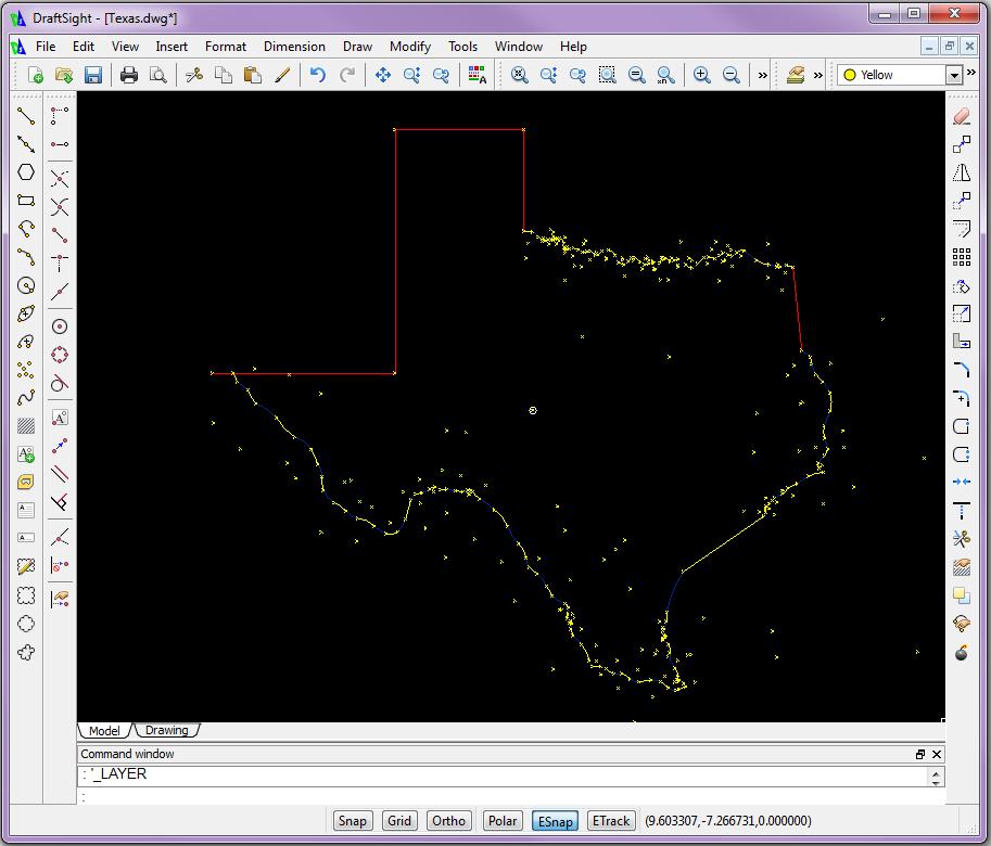
There are four steps in sequence in your CAD system:
- Create and select a new layer
- Create a point at program zero
- In sequence of machining operation:
- Create one point for linear motion
- Create two points for rapid motion
- Create one line for clockwise motion
- Create two lines for counter-clockwise motion
- For arcs less than 180 degrees, create a point at arc end (or intersection on arc) followed by a point at arc center
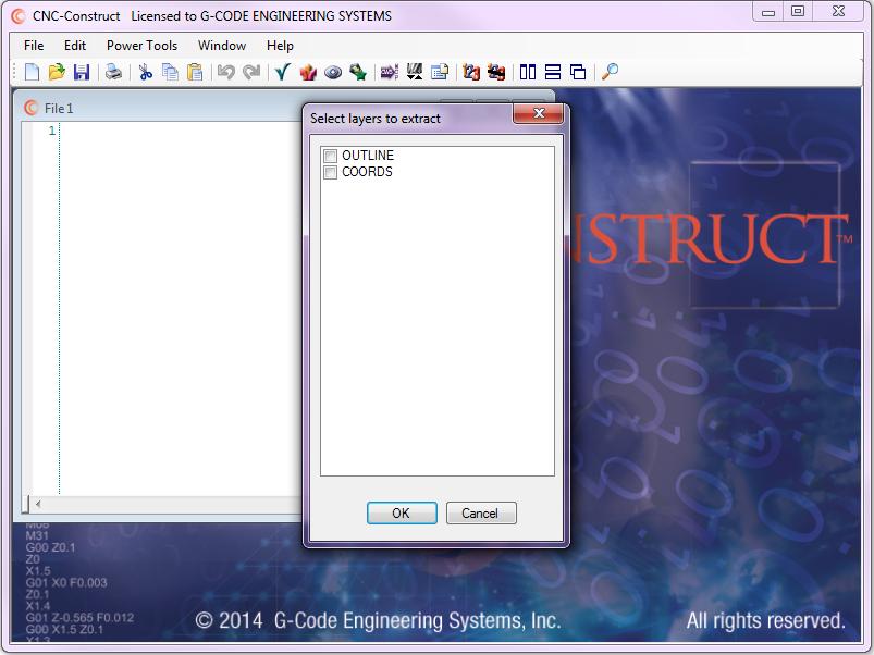
- Create and select a new layer for each corresponding prompt section of the coordinate work sheet.
- Save the part as DXF (ASCII)
CNC Construct was developed to extract layer information and coordinates from points and lines, translate the coordinates relative to program zero, assign motion, and create a Coordinate Work Sheet file type automatically.
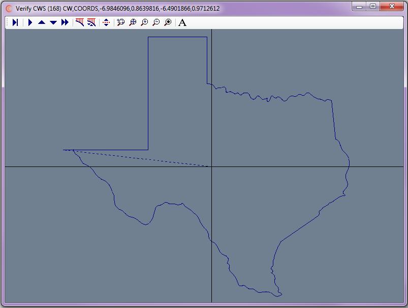
Verify Coordinate Work Sheet features and options:
- Auto scaled to fit window
- Single Step, Fast Forward, or Auto Play with Speed Control
- Rapid motion is displayed as dashed lines
- Color of verification is changed at prompt changes in coordinate work sheet
- Coordinates of tool path are sequentially displayed at top of screen
- Crosshairs at program zero
- Zoom Window, Zoom in, Zoom out, Pan Center, Reset scale to fit window
- Clear screen, Auto clear screen
- Toggle rapid on/off
- Enter text for additional programming prompt capability
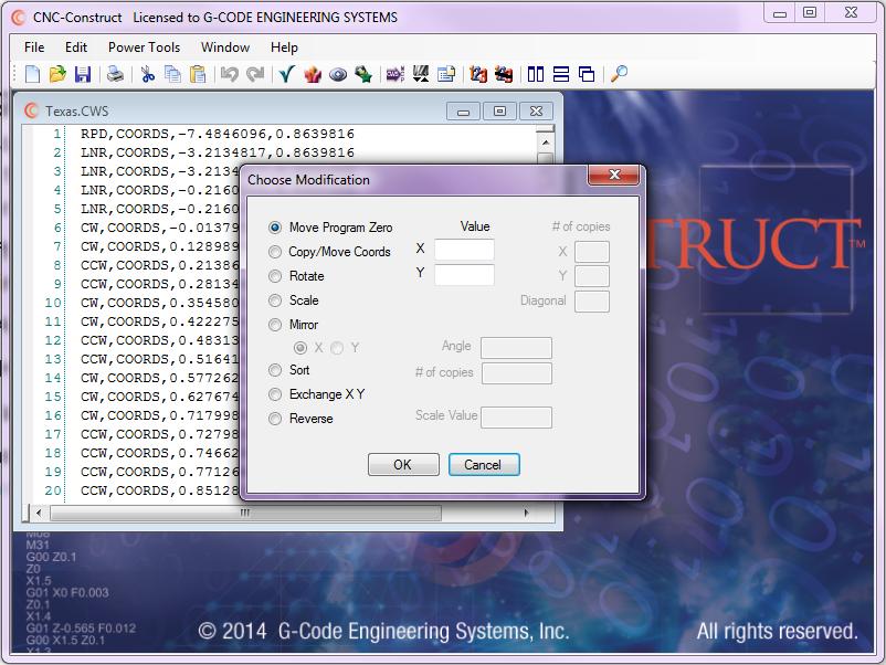
Modify Coordinate Work Sheet features and options:
- Move program zero
- Move coordinates
- Copy coordinates horizontally, vertically, and diagonally
- Scale coordinates
- Rotate coordinates
- Rotate with Copy
- Mirror Coordinates about horizontal or vertical axis
- Sort coordinates by programming prompt
- Exchange X-Y coordinates
- Reverse sequence of coordinates
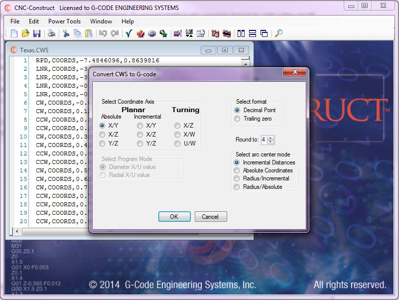
Convert Coordinate Work Sheet to G-code features and options:
- Use X-Y, X-Z, or Y-Z words
- Planar or turning
- If turning, either radial or diameter X/U coordinates
- Absolute (G90) or incremental (G91) coordinates
- If turning, absolute (X-Z), incremental (U-W), or combo (U-Z)
- Decimal or trailing zero
- Round coordinates to 2-5 places
- Arc designation with absolute, incremental, or radius
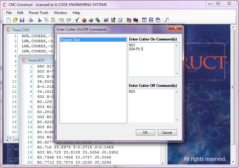
CUTTER ON/CUTTER OFF COMMANDS
Cutter on and cutter off commands are those commands that tell the machine to start the material removal operation. Waterjet, Laserjet, Plasmajet, Torch, and Milling operations would incorporate these commands.
These cutter on/cutter off commands do not change throughout the entire program for planar operations. Conversely, milling opertions might include different cutter on/cutter off commands for different tools, or different part features.
CNC Construct was developed to perform the highly repetitive task of inserting these user provided commands into the G-Code program. Prompt changes in the CWS file are included in the G-Code file. These changes allow the user to make changes to the cutter on/cutter off commands accordingly.
Logically, cutter on commands are inserted immediately after the rapid motion commands (G00). Cutter off commands are inserted immediately prior to those same rapid motion commands.
Program beginning, program stop/tool change, and program end commands
CNC Construct was developed to paste the program beginning, program stop/tool change, and program end commands into the G-Code program from a template file.
Typically, for many like machine tools, this section of the G-Code program does not change. That is to say most or all milling centers will have the same program beginning, program stop/tool change, and program end commands. Accordingly, all turning operations will have the same program beginning, program stop/tool change, and program end commands.
Edit and Number G-Code program
CNC Construct has a powerful text editor that allows the user to make edits to the program as necessary. For example to change the program number, speeds, feed rates, tool numbers, cutter length compensation, cutter diameter compensation, add comments, remove redundant commands etc.
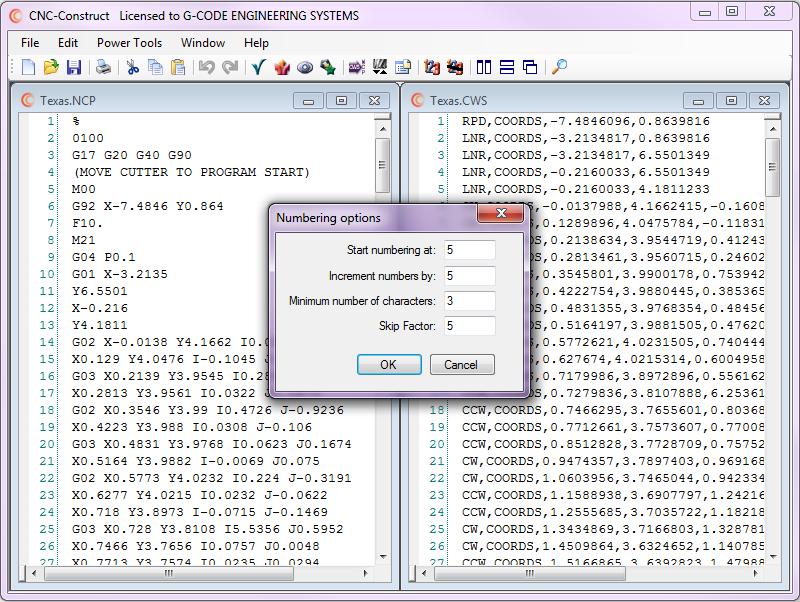
And if necessary, CNC Construct will number, renumber, and un-number the G-Code program.
