Planar Examples
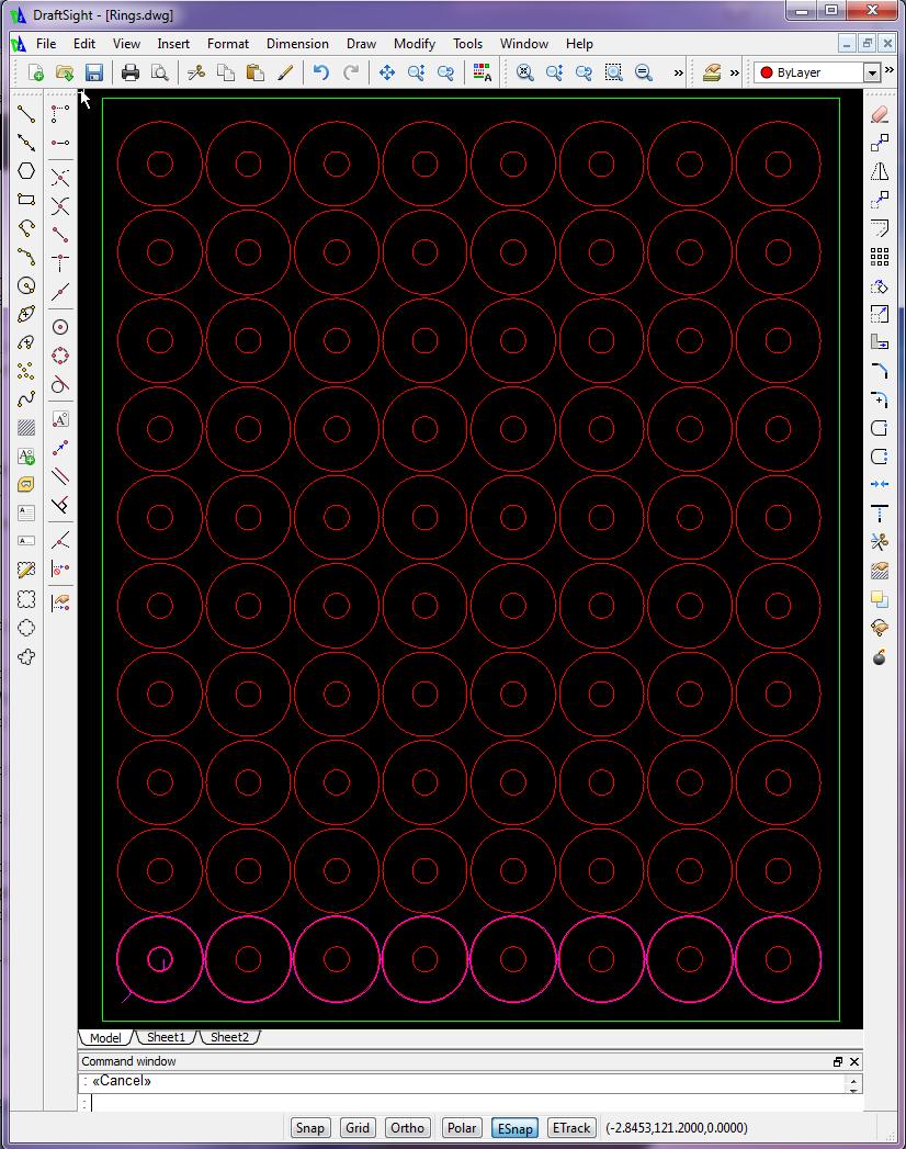
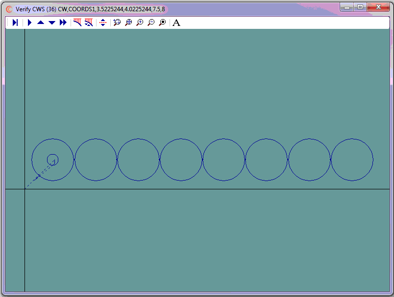
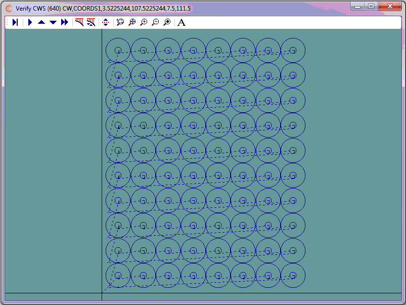
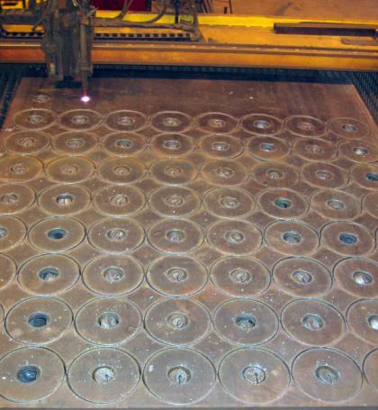
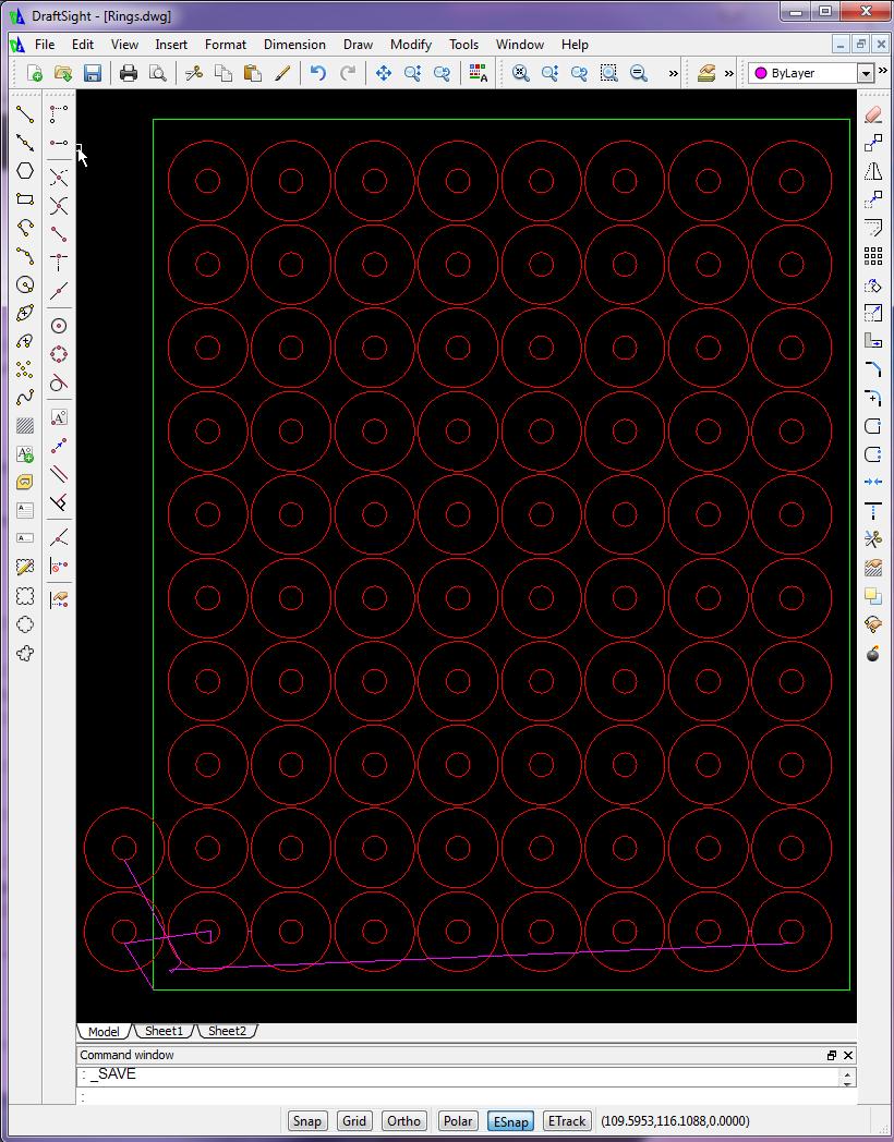
This programming job had three requirements, 1) to penetrate the material at least 1" away from the profile and 2) to cut the eight OD profiles in one continuous operation, and 3) to cut each row at a time, i.e., 8ID profiles then 1 continuous OD profile x 10 rows.
- The parts were separated center to center 11.5" both horizontally and vertically
- Center line programming was used
- The kerf was 0.25"
- The tool path was offset from part by 0.125"
- Cutter on/cutter off commands were M70/M73 respectively
The steps to complete this programming job were as follows:
- Use CAD to generate cutter coordinates for the first ID
- Use CAD to generate the cutter coordinates for the first continous OD profile
- Use CNC Construct to extract the coordinates from CAD and automatically create the CWS file
- Use CNC Construct to copy the first ID 11.5" x 7 times horizontally
- Use CNC Construct to copy the first row 11.5" x 9 times vertically
- Use CNC Construct to convert the CWS file to G-Code (absolute coordinates)
- Use CNC Construct to insert cutter on/cutter off commands
- Use CNC Construct to paste the programming beginning and program end commands from a template
- Use CNC Construct to edit the program as necessary
- Use CNC Construct to number the program (begin with 5, characters = 3, increment = 5, skip factor = 5)
View 825 line G-Code Program »
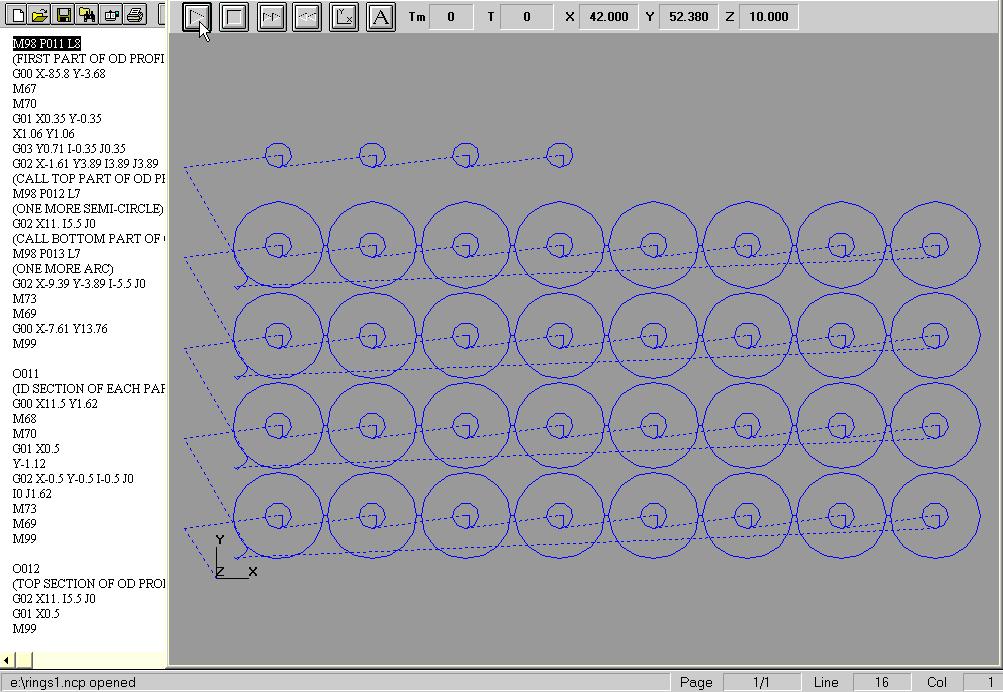
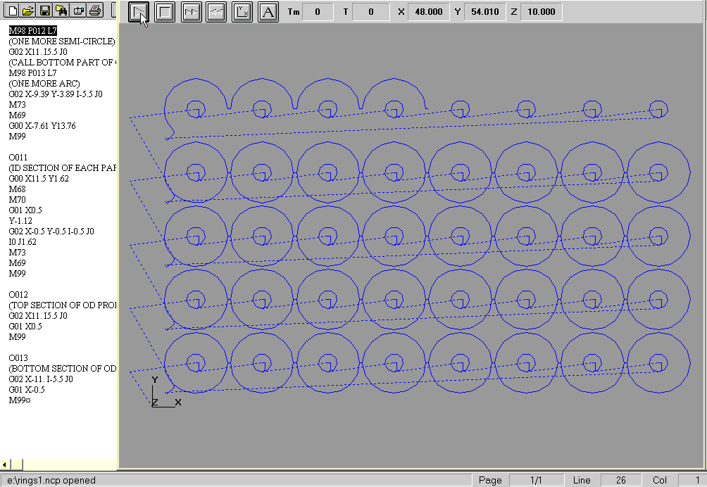
By using subroutine programming, the program to cut the 80 parts can be significantly reduced in size.
- The parts were separated center to center 11.5" both horizontally and vertically
- Cutter comp left, right, and cancel were M67, M68, and M69 respectively
- Cutter on/cutter off commands were M70/M73 respectively
- One subroutine to rapid to and cut a single ID profile
- One subroutine to cut a single top semi-circle and linear to next semi-circle of OD profile
- One subroutine to cut a single bottom semi-circle and linear to next semi-circle of OD profile
- One subroutine to cut a row (includes the calling of three afforementioned subroutines)
- One main routine that calls the afforementioned subroutine 10 times
The steps to complete this programming job were as follows:
- Use CAD to generate cutter coordinates for the rapid to and cut of single ID profile
- Use CAD to generate cutter coordinates for the rapid to and cut of the OD profile
- As part of step 2, use CAD to generate a single top semi circle with linear move
- As part of step 2, use CAD to generate a single bottom semi-circle with linear move
- As part of step 2, use CAD to generate rapid motion to next row
- Use CNC Construct to extract the coordinates from CAD and automatically create the CWS file
- Use CNC Construct to convert the CWS file to G-Code (incremental coordinates)
- Use CNC Construct to edit the program and subroutines as necessary
View main program and subroutines »
Wire EDM jobs provide the most simple of programming jobs. Cutter coordinates are converted to G-code and the program is 99% complete.
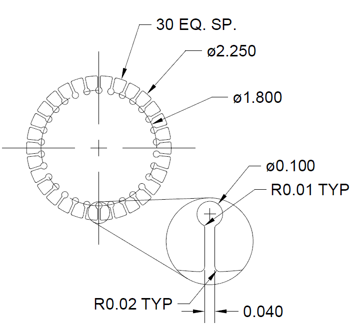
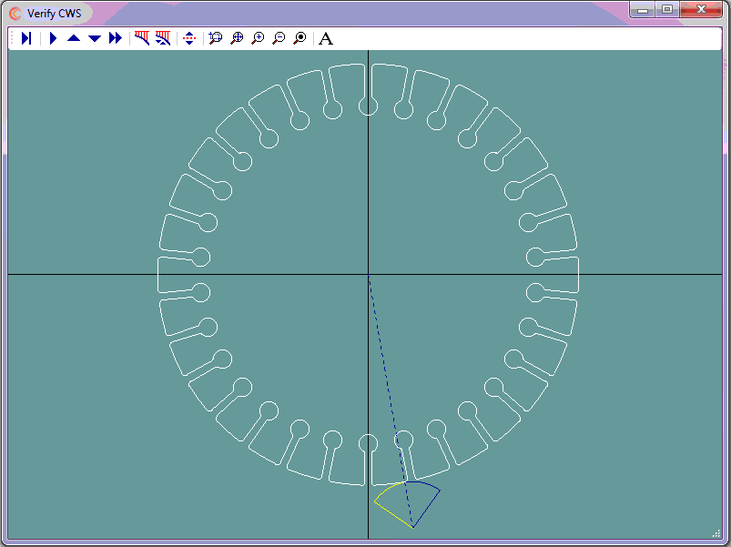
- The part can be viewed by selecting the link below
- Cutter left (G41) compensation will be used
- There are no cutter on/cutter off commands
The steps to complete this programming job were as follows:
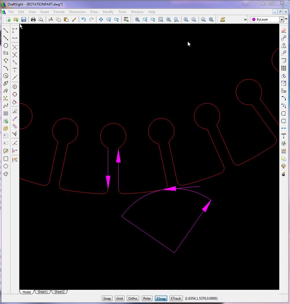
- Use CAD to design the lead in/lead out tool paths
- On its own layer, use CAD to generate cutter coordinates for the lead in
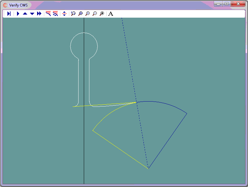
- On its own layer, use CAD to generate cutter coordinates for one "feature of rotation"
- On its own layer, use CAD to generate cutter coordinates for the lead out
- Use CNC Construct to extract the coordinates from CAD and automatically create the CWS file
- Use CNC Construct to rotate the one "feature of rotation" -12 degrees with 29 copies
- Use CNC Construct to convert the CWS file to G-Code (5 decimal places, use Radius for arcs)
- Use CNC Construct to paste program beginning and program end commands
- Use CNC Construct to edit the program as necessary
View 252 Line G-Code Program »
Because of the resulting finish on the edge of parts cut with plasma, it is common practice to cut outer perimeters clockwise and inner perimeters counter clockwise using cutter left compensation for both.
In general, machine tools can only cut straight lines (G01), or arcs (G02/G03).
CAD has the power of placing multiple points on curves. CNC Construct has the ability to extract these points and convert them to linear motion.
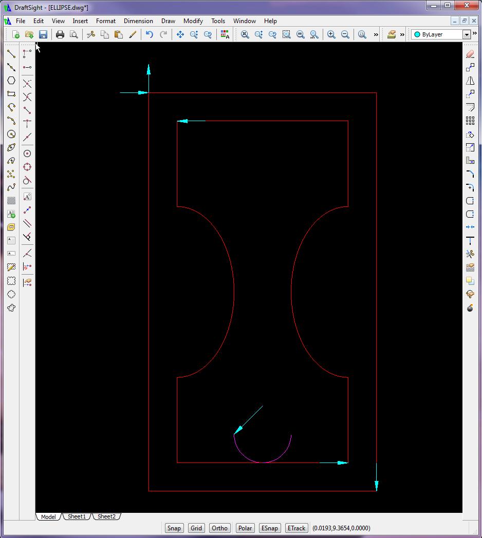
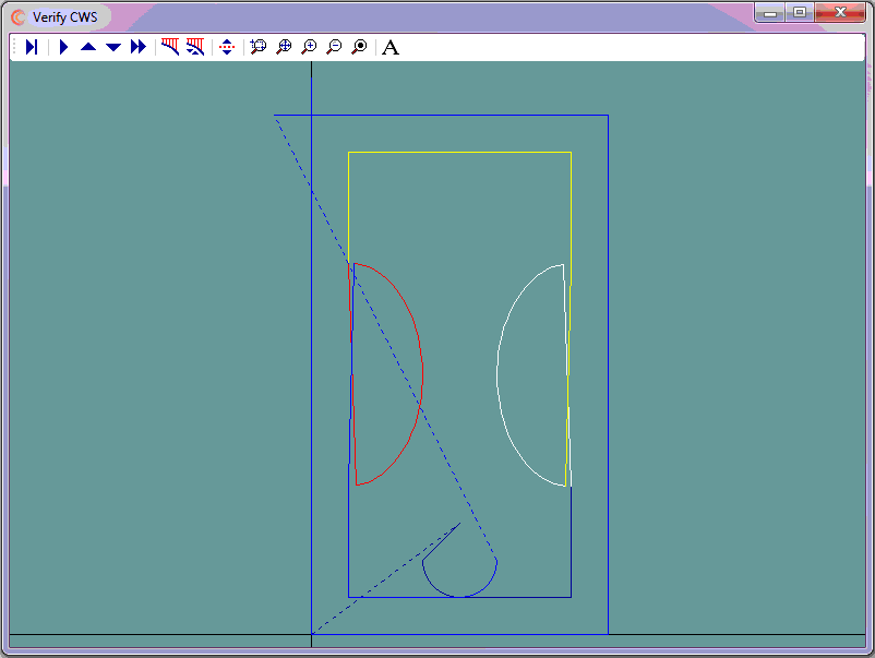
The problem is that CAD may generate these points opposite to the designed tool path, i.e., CAD may start placing points at the curve end and finish placing points at the start.
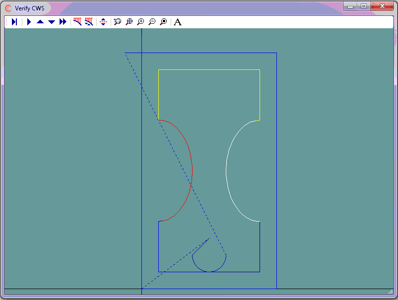
This example presents how to use CNC Construct to solve this problem.
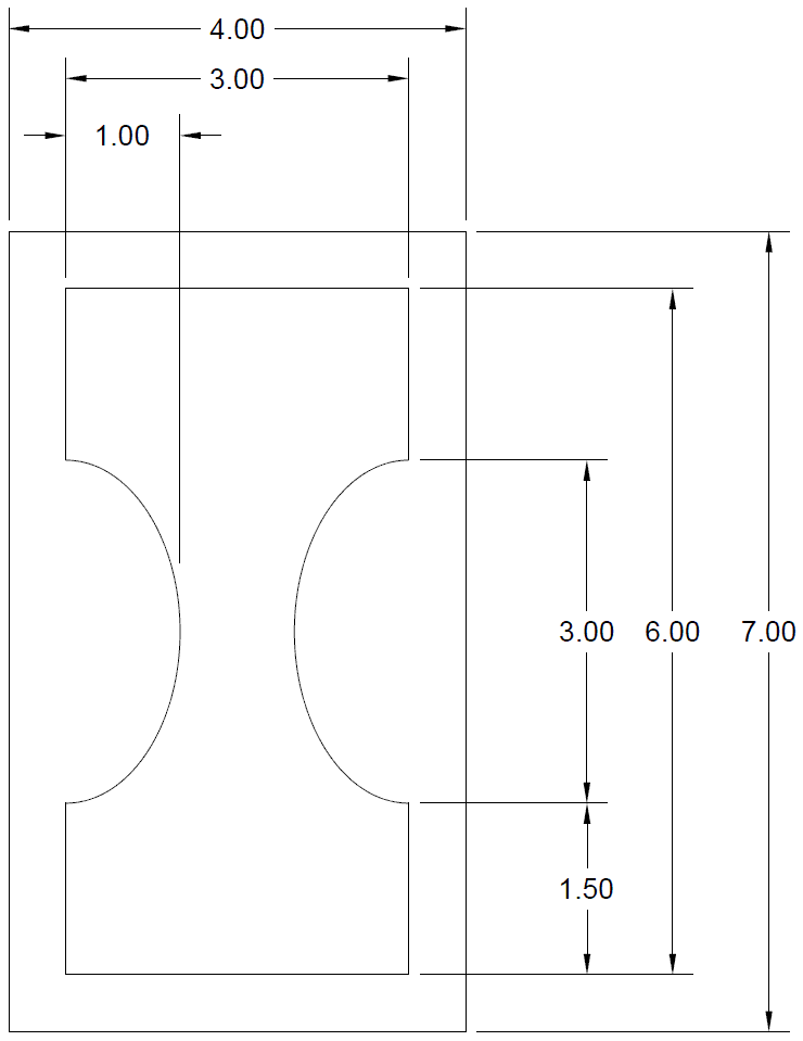
- The part can be viewed by selecting the link below
- Cutter left (M67) compensation will be used for both inner and outer outer profiles
- Cutter compensation cancel command is M69
- Cutter on/cutter off commands are M65 and M66 respectively
The steps to complete this programming job were as follows:
- Use CAD to design the lead in/lead out tool paths
- On its own layer, use CAD to generate cutter coordinates for program zero, the lead in, and the lower right portion of the inner profile
- On its own layer, use CAD to generate cutter coordinates for the right ellipse (0.1" increments).
- Returning to the initial layer, use CAD generate cutter coordinates for the upper part of the inner profile
- On its own layer, use CAD to generate cutter coordinates for the left ellipse (0.1" increments)
- Return to initial layer, use CAD to generate cutter coordinates for lower part of inner profile and outer profile
- Use CNC Construct to extract the coordinates from CAD and automatically create the CWS file
- Use CNC Construct to reverse the sequence of both ellipses
- Use CNC Construct to convert the CWS file to G-Code (2 decimal places)
- Use CNC Construct to insert compensation on-cutter on and compensation off-cutter off commands
- Use CNC Construct to paste program beginning and program end commands
- Use CNC Construct to edit the program as necessary
View G-Code Program »
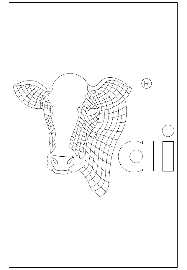
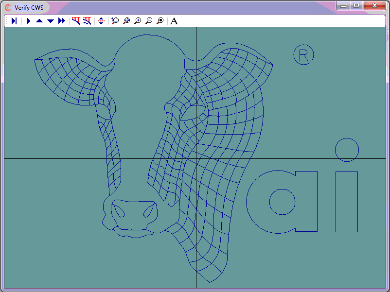
Although engraving jobs are done on a mill, they are the equivalent programming problem as any waterjet, laserjet, or plasmajet because the cutter on/cutter off commands do not change throughout the program.
- The part can be viewed by selecting the link below
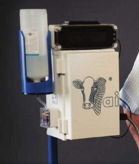
- The company logo is to be engraved to a depth of -0.02" with a 1/16" flat end mill on the cover of a 7" x 11" FIBOX
- Cutter on/cutter off commands are G01 Z-0.02 and G00 Z0.1 respectively
The steps to complete this programming job were as follows:
- Use CAD to trace the art work with arcs and lines
- On its own layer, use CAD to generate cutter coordinates
- Use CNC Construct to extract the coordinates from CAD and automatically create the CWS file
- Use CNC Construct to convert the CWS file to G-Code (4 decimal places)
- Use CNC Construct to insert cutter on and cutter off commands
- Use CNC Construct to paste program beginning and program end commands
- Use CNC Construct to edit the program as necessary
View G-Code Program before any edits were made »
